IM 2
Written by Matt Johnson of 86 Central

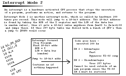
A brief introduction to Interrupt Mode 2 was given on the top. Once you set up IM 2, IM 1 no longer applies. It does not jump to $38 every interrupt. This is what happens when an interrupt occurs and we are in Interrupt Mode 2:
- An interrupt occurs
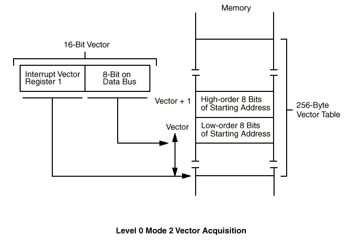
- The CPU will then form a 16-bit address where the
IRegister is the Most Significant byte and the Least Significant Byte is a number received from the data bus. - A 256 byte vector table must be created in the range of
$xx00to$xxff, wherexxis theIregister. The 256 bytes cover all possible combinations that can occur by the random value received from the data bus. - Once the 16-bit address is formed, a jump will occur to this vector table. It jumps to an even address and uses two bytes to form another 16-bit address.
- Then it performs a jump to this newly created 16-bit address.
- Since the jump is basically random in this 256 byte region, all the bytes
in the table values will be filled with the same value, for example,
$8f. That way a when it jumps to the table it will form a 16-bit address of$8f8f, no matter where it jumps to in this table (which is always an even address), a jump to$8f8f

IM 2 is a fast interrupt mode, but the handler can be optimized even
more if you do not wish to use it with TSR's. This is explained in the
Advanced Interrupt section. It also gives you more available ram for the
interrupt handler when compared to the 200 byte limit of the IM 1 user
routine ($d2fe, rememember?)
By now you probably wish to see an interrupt mode 2 template. Here it
comes. In this template, it will set up the basic interrupt handler. When
the interrupt code is complete, it will then jump to $66 to finish the
normal TI-OS interrupt. This allows IM 2 to be used in the TI-OS (as a
TSR), or in an asm program. In my Advanced Interrupts section, I will show
you a lightning fast IM 2 interrupt handler that needs not jump $66. This
will only work in asm programs (it would crash TI-OS obviously), but allows
for lightning fast interrupt handlers (i.e. flickerless grayscale!).
Basic Interrupt Mode 2 Template
#include "ti86asm.inc"

int_addr equ $F8F8                      ;Start of interrupt code

.org _asm_exec_ram                      ;Set instruction counter to $D748 (start of all asm programs)

 ld hl,$FA00                            ;Source = $FA00 (Start of vector table)
 ld de,$FA01                            ;Destination = $FA01
 ld (hl),$F8                            ;Set first byte so it is copied to all of them ($F8F8)
 ld bc,257                              ;257 bytes (size of vector table)
 ldir                                   ;(DE) <- (HL), BC=BC-1, Loop till B=0

 ld hl,int_copy                         ;Source = interrupt routine
 ld de,int_addr                         ;Destination = $F8F8 (as specified in vector table)
 ld bc,int_end-int_start                ;Length of custom interrupt routine
 ldir                                   ;(DE) <- (HL), BC=BC-1, Loop till B=0

 ld a,$FA                               ;Set up address of vector table
 ld i,a                                 ; MSB = $FA
                                        ; LSB = (byte supplied by data bus - random)
 im 2                                   ;Set interrupt mode 2

 ret                                    ;Return

int_copy:
 .org int_addr                          ;Set instruction counter to $F8F8 (start of int handler)

int_start:
 ex af,af'                              ;Exchange af with alternate register af'
 exx                                    ;Exchange all other reg's with alternate reg's

; ---------------------------------------------------------
; CODE GOES HERE
; ----------------------------------------------------------

 jp $66              ;jump to normal handler so it can do its things

int_end:

.end
Notes
The jp $0066 at the end of IM 2 routine allows you to hand over control
to the default interrupt handler normally at $0038. All the interrupt handler
does at $0038, though, is exchange (ex af,af' / exx) and check to see if
the user routine is installed (which we don't need cause we are using IM
2 for our interrupt code). Since an exchange is performed at the end of
the IM 1 interrupt handler ($008a and $008b), and we skip over the initial
exchange at $0038, we only need to exchange the registers once in our interrupt
handler code (right after int_start).
When working with Interrupt Mode 2 as a TSR, we have no way of knowing
what RAM page we are at. That means that we need all the ram for the vector
table and the interrupt handler routine in RAM PAGE 0. As you see, this
vector table starts at $fa00 and the interrupt handler starts at $f8f8.
This could cause the system to become unstable or crash if an asm program
is over 8,624 bytes (it would overwrite the vector table), or if the hardware
stack was over 257 bytes (it would overwrite the interrupt handler code).
This is extrememly unlikely, I haven't had it crash once (well, once I
got everything working OK, ;) )
Remember, this code right here works perfectly for TSR's. In other words,
our IM 2 custom interrupt handler can easily run in the background along
with the TI-OS, since it performs a jump that finishes the rest of the
standard interrupt handler code ($0038 normally - we skip to $0066 however,
see above). However, for ultimate speed, the fastest interrupt handler
ever shall be in my Advanced Interrupt section. This ULTRA fast IM 2 code
will only work in asm programs, it cannot be used in TSR's. However, it
is fast and handles grayscale with virtually no flicker. I am talking about
the potential of flickerless 8-level grayscale!! See the advanced section
for more details.
The IM 2 TSR example that follows will be just like the IM 1 user routine TSR in the earlier example.
#include "ti86asm.inc"

int_addr equ $F8F8                      ;Start of interrupt code

.org _asm_exec_ram                      ;Set instruction counter to $D748 (start of all asm programs)

 ld hl,$FA00                            ;Source = $FA00 (Start of vector table)
 ld de,$FA01                            ;Destination = $FA01
 ld (hl),$F8                            ;Set first byte so it is copied to all of them ($F8F8)
 ld bc,257                              ;257 bytes (size of vector table)
 ldir                                   ;(DE) <- (HL), BC=BC-1, Loop till B=0

 ld hl,int_copy                         ;Source = interrupt routine
 ld de,int_addr                         ;Destination = $F8F8 (as specified in vector table)
 ld bc,int_end-int_start                ;Length of custom interrupt routine
 ldir                                   ;(DE) <- (HL), BC=BC-1, Loop till B=0

 ld a,$FA                               ;Set up address of vector table
 ld i,a                                 ; MSB = $FA
                                        ; LSB = (byte supplied by data bus - random)
 im 2                                   ;Set interrupt mode 2

 ret                                    ;Return

int_copy:
 .org int_addr                          ;Set instruction counter to $F8F8 (start of int handler)

int_start:
 ex af,af'                              ;Exchange af with alternate register af'
 exx                                    ;Exchange all other reg's with alternate reg's

; ---------------------------------------------------------
 ld hl, $FC00        ; HL points to display
 ld de, CalcPIC      ; DE points to start of sprite
 ld b, 9             ; Nine rows

Loop:
 ld a, (de)          ; Get byte from sprite
 ld (hl), a          ; Display byte on screen

 inc de              ; Next byte of sprite

 ld a, l
 add a, 16           ; Add 16 to L (goes to next row)
 ld l, a

 djnz Loop
; ----------------------------------------------------------

 jp $66              ;jump to normal handler so it can do its things

CalcPIC:
        .db %11101110
        .db %01000100
        .db %01001110
        .db %00000000
        .db %11100100
        .db %10101000
        .db %01001100
        .db %10101010
        .db %11100100

int_end:

.end
More from z80 » Advanced
All The Ports // APD // Assembler Directives // Entry Stack // User Fonts // IM 1 // IM 2 // Index, Shadow, and Other Registers // User Interrupt // Morphic Code // On-Off // Reading Keypresses from Port // Shift and Rotate // Simulating Key Presses // Sound // Square-Root Programs // System Flags of TI-OS